Using the Lidl Livarno Lux Zigbee gateway with Zigbee2MQTT
link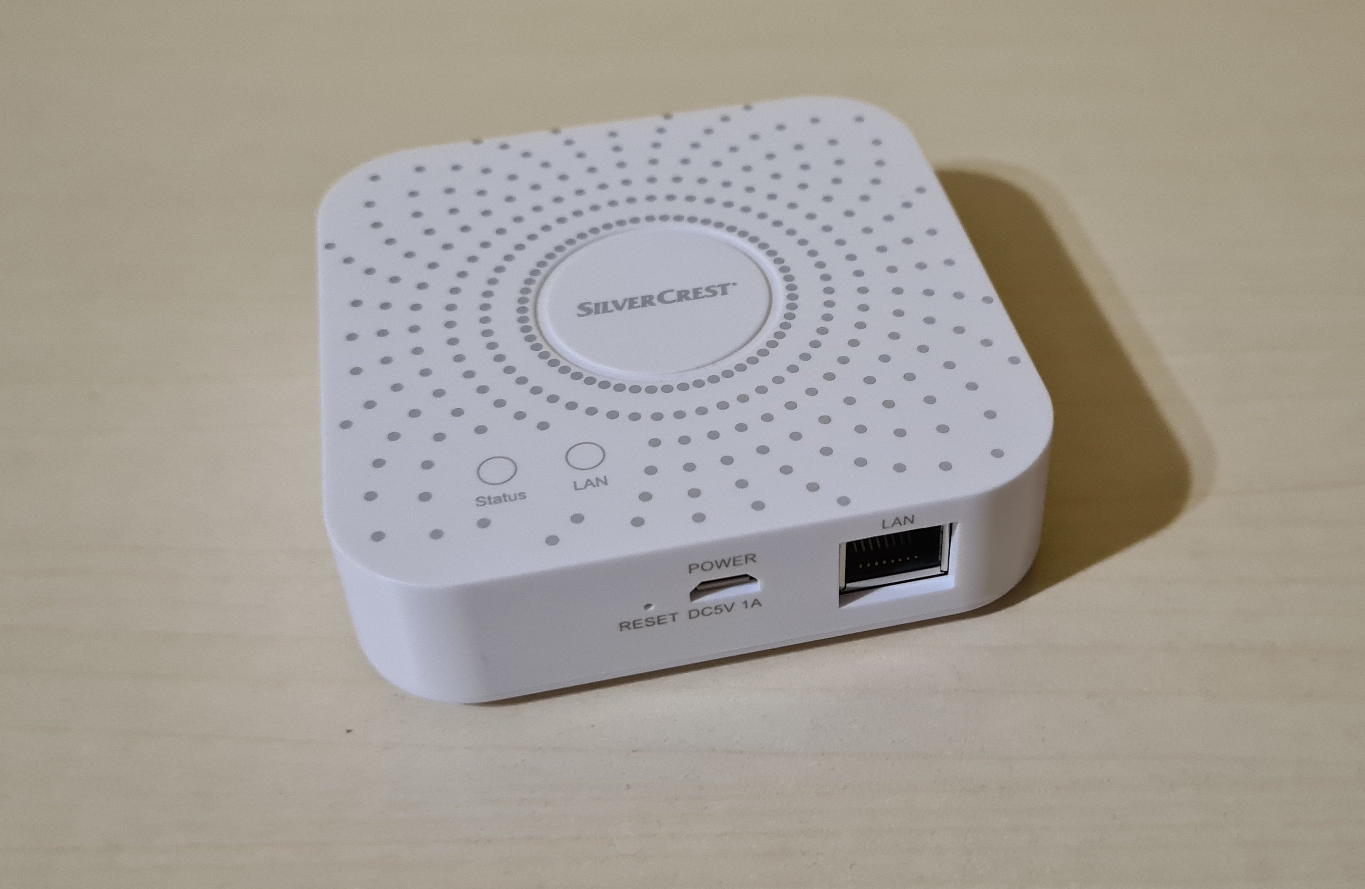
A few months ago I bought a set of 3 ZigBee RGB lightbulbs and a gateway from Lidl. The lightbulbs are fine, but the gateway in it’s original form only works with the proprietary Tuya ecosystem. This means that it connects to the Tuya cloud, I have to use the Tuya apps to control my devices. Additionally I cannot use any non-Tuya devices in my network, because they are not compatible with the Tuya ecosystem.
A much better solution is to use the open-source Zigbee2MQTT software. Zigbee2MQTT supports most of th Zigbee devices on the market, and it is not limited to Tuya devices. The usual setup for Zigbee2MQTT is to use an USB to Zigbee adapter, which you plug into a Raspberry Pi running Zigbee2MQTT. But since I have a gateway from Lidl, I can use it as a bridge between the Zigbee network and the MQTT network.
To achieve that, we will need to remove the Tuya software from the gateway and upgrade the EZSP firmware to suit Zigbee2MQTT. This is because Zigbee2MQTT needs at least the EZSP version 8 (EmberZNet Serial Protocol).
The first part of this guide is based on two awesome guides by Paul Banks:
So If you are already using the gateway with ZHA you can skip straight to step 8.
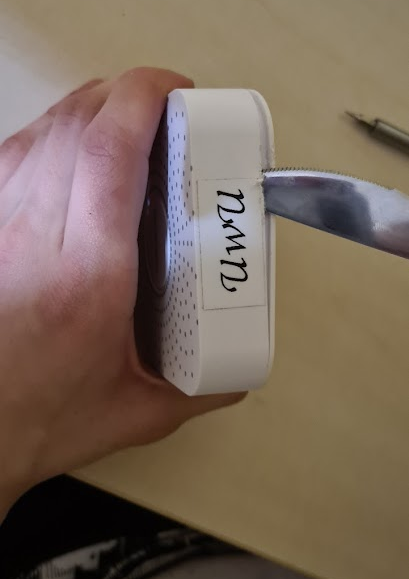
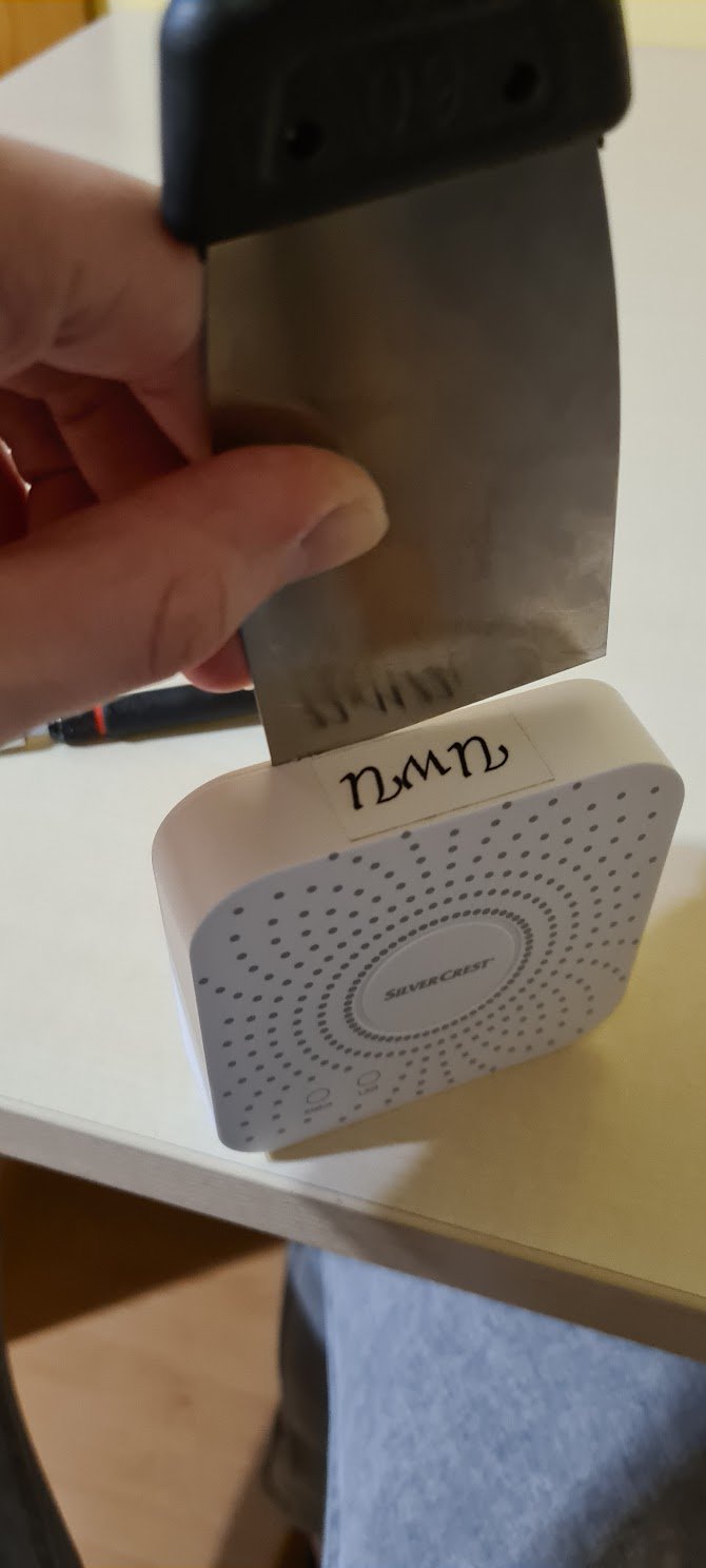
Step 0: Disassemble the gateway
linkUse a sharp object to pry open the enclosure. It is held by two plastic clips on each side, without any screws.
Step 1: Solder pin headers to the debug port
linkSolder standard 2.54mm pin headers to the exposed holes.

Step 2: Connect a serial to USB adapter to the header
link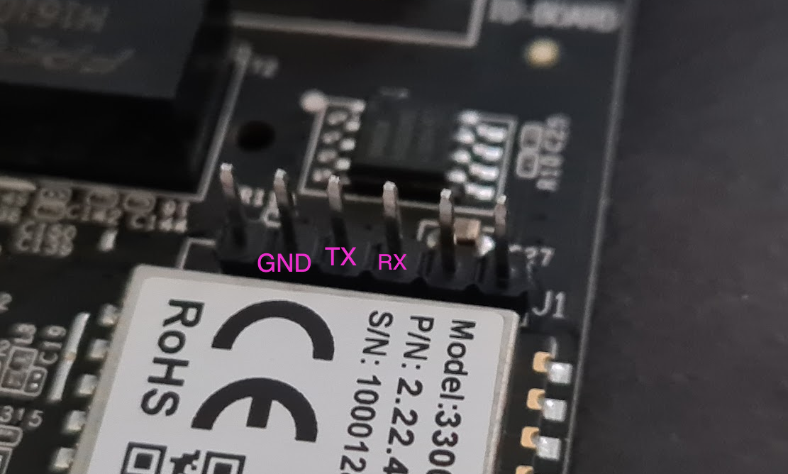
Connect them like this
| USB serial | Debug header |
|---|---|
| GND | GND |
| TX | RX |
| RX | TX |
Step 3: Enter the bootloader
linkConnect the serial dongle to your computer and start up your favorite serial monitor (tio, minicom, putty, screen etc.) and open the serial port with a baudrate of 38400, databits set to 8 and no parity nor flow control.
After starting the serial monitor power up the gateway and start pressing the ESC key in the serial monitor.
If you successfully entered the bootloader you should see a <RealTek> prompt. The output will look like this:
tio /dev/ttyUSB0 -b 38400 -d 8 -p none -s 1 --flow none
[tio 20:54:59] tio v1.32
[tio 20:54:59] Press ctrl-t q to quit
[tio 20:54:59] Connected

Booting...

@@@@@@@@@@@@@@@@@@@@@@@@@@@@@@@@@@@@@@@@@@@@@@@@@@@@@@@@@@@@@@@@@@@@@@@@@@@@@@@@
@
@ chip__no chip__id mfr___id dev___id cap___id size_sft dev_size chipSize
@ 0000000h 0c84018h 00000c8h 0000040h 0000018h 0000000h 0000018h 1000000h
@ blk_size blk__cnt sec_size sec__cnt pageSize page_cnt chip_clk chipName
@ 0010000h 0000100h 0001000h 0001000h 0000100h 0000010h 000004eh GD25Q128
@
@@@@@@@@@@@@@@@@@@@@@@@@@@@@@@@@@@@@@@@@@@@@@@@@@@@@@@@@@@@@@@@@@@@@@@@@@@@@@@@@
DDR1:32MB

---RealTek(RTL8196E)at 2020.04.28-13:58+0800 v3.4T-pre2 [16bit](400MHz)
P0phymode=01, embedded phy
check_image_header  return_addr:05010000 bank_offset:00000000
no sys signature at 00010000!

---Escape booting by user
P0phymode=01, embedded phy

---Ethernet init Okay!
<RealTek>
If you miss and start booting Linux normally: Don’t worry, unplug the gateway and try again!
Step 4: Extract the values needed to obtain the root password
linkTo extract the root password we will need to read two values from the flash memory: the KEK and the AUSKEY.
To read the KEK run the following two commands via the serial connection:
FLR 80000000 401802 16
DW 80000000 4
Save the one line of output somewhere, then this ot get the AUSKEY:
FLR 80000000 402002 32
DW 80000000 8
The output of the above commands should look like this:
<RealTek>FLR 80000000 401802 16
Flash read from 00401802 to 80000000 with 00000016 bytes	?
(Y)es , (N)o ? --> y
Flash Read Successed!
<RealTek>DW 80000000 4
80000000:	3D45F729	6C5F3CA5	3C5D4B2A	6F57326F


<RealTek>FLR 80000000 402002 32
Flash read from 00402002 to 80000000 with 00000032 bytes	?
(Y)es , (N)o ? --> y
Flash Read Successed!
<RealTek>DW  80000000 8
80000000:	A9AE7C60	D6C475F9	A1F9BD52	68AF5392
80000010:	F7333B4A	76308247	D3DDD4FC	30E1874C
Save the two lines of output somewhere. Now you can use Paul’s Python script to decode the root password or just paste the values here:
Root password calculator
link
Step 5: Install a serial to TCP bridge on the gateway
linkDownload the compiled serial to TCP bridge and in the directory of the gateway, run the following command:
cat serialgateway.bin | ssh -p2333 -oHostKeyAlgorithms=+ssh-rsa root@<IP of the gateway> "cat >/tuya/serialgateway"
This command will copy the binary to /tuya/serialgateway on the gateway. Remember to replace <IP of the gateway> with the IP of the gateway.
Step 6: Modify the boot script to start the TCP bridge
linkAfter you upload the TCP bridge binary, you will need to modify the boot script to start it instead of the default Tuya binary. To do this connect via ssh (use the ssh command on macOS and Linux or PuTTY on Windows).
ssh -p2333 -oHostKeyAlgorithms=+ssh-rsa root@<IP of the gateway>
Inside the SSH session, run the following commands:
if [ ! -f /tuya/tuya_start.original.sh ]; then cp /tuya/tuya_start.sh /tuya/tuya_start.original.sh; fi

cat >/tuya/tuya_start.sh <<EOF
#!/bin/sh
/tuya/serialgateway &
EOF
chmod 755 /tuya/serialgateway
Step 7: Reboot the gateway
linkJust cut the power to the gateway and plug it back in. Or alternatively you can use the reboot command via SSH.
In this state the bridge is ready to be used with ZHA (Homeassistant’s native Zigbee support), you just have to point it to tcp:://<ip of the bridge>:8888. But we want to use it with Zigbee2MQTT, so we need to update the EZSP firmware on the ZigBee chip.
Step 8: Install bellows and verify the current version of the firmware
linkFirstly make sure you have Python 3 installed on your system and added to your PATH.
Then install the bellows package.
$ pip install bellows # alternatively use `pip3 install bellows`
Then run the bellows command get the current version of the firmware:
bellows -d socket://<ip of the gateway>:8888 info
Remember to replace <ip of the gateway> with the IP of the gateway. If everything went correctly you should see something like this:
$ bellows -d socket://192.168.1.3:8888 info
... # truncated for brevity

Manufacturer:
Board name:
EmberZNet version: 6.5.0.0 build 188
As you can see the EZSP version is 6.5.0.0 so it will cause Zigbee2MQTT to fail to pair with devices.
Step 9: Enter the bootloader of the Zigbee module
linkNow we will use bellows to switch the Zigbee module to the bootloader mode so that we can flash it. This is diffrent from the bootloader of the gateway, because the Zigbee module has it’s own ARM processor, separate to the one running Linux.
bellows -d socket://<ip of the gateway>:8888 bootloader
It should output a success message:
$ bellows -d socket://192.168.1.3:8888 bootloader
Manufacturer:
Board name:
Current EmberZNet version: 6.5.0.0 build 188
bootloader version: 0x1800, nodePlat: 0x04, nodeMicro: 0x18, nodePhy: 0x0f
bootloader launched successfully
Step 10: Flash newer firmware on the Zigbee module
linkTo actually flash the firmware we will need two extra files:
- the
upgrade_ncp.pyscript by Paul Banks: Download here - the firmware itself -
NCP_UHW_MG1B232_678_PA0-PA1-PB11_PA5-PA4.gblDownload here
Put them in one directory, and before running the script first install xmodem:
$ pip install xmodem
Then run the script to perform the firmware upgrade:
$ python upgrade_ncp.py <ip of the gateway> NCP_UHW_MG1B232_678_PA0-PA1-PB11_PA5-PA4.gbl
The script will ask you to enter the word UPGRADE to confirm, after that it’s output should look like this:
Attempting upgrade...
Entering upload mode...
Waiting for XMODEM...
Uploading firmware...
Upload complete. Starting new firmware...
Done
And this way your gateway is ready to be used with Zigbee2MQTT.
Step 11: Configure Zigbee2MQTT to use the gateway
linkThe last step in setting up the gateway is to configure Zigbee2MQTT itself. FOr installing it please follow the appropriate guide on the Zigbee2MQTT website.
To use the gateway drop these lines into configuration.yaml:
serial:
  port: tcp://192.168.1.3:8888
  adapter: ezsp
Thanks for reading!